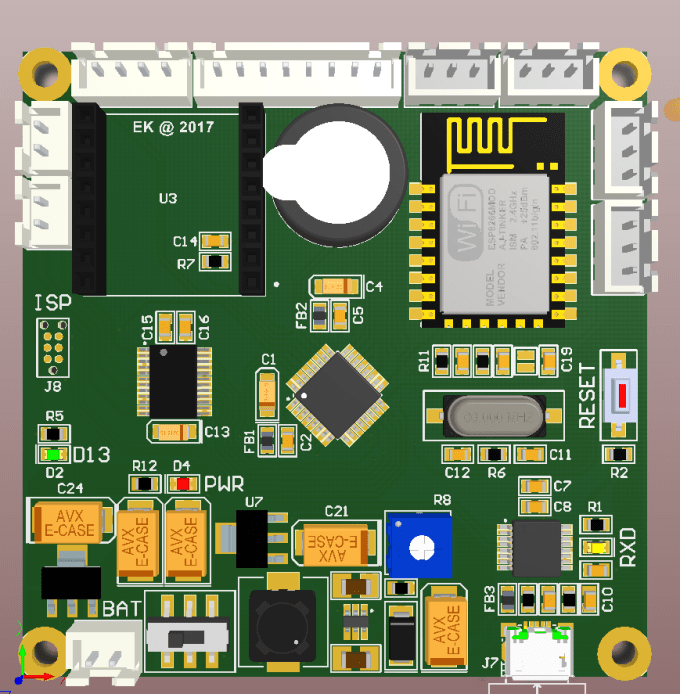

Apart from the standards issued by IPC, there will be some special cases like soldering reflow instructions, keep out areas, courtyards, etc.
Do not neglect manufacturer recommendations. Hence it is mandatory to stick to the footprint creation guidelines in such scenarios. This process is time-consuming and might lead to errors. A land pattern should only be created from scratch if the package type is not found in the library. 
We have options to modify the existing package footprint to suit our requirements.
Whenever it is possible to use a common package type, use it. A few tips mentioned in this standard are: The IPC-7351 standard provides instructions to utilize existing common footprints and to create new ones. It also provides guidelines to make space for inspection, testing, and rework of the components. The solder joint quality should meet the guidelines set by J-STD-001 as well. This standard ensures maximum solder joint quality after the component placement. The IPC-7351 depicts the requirements for surface mount designs and land pattern standards. The land pattern gives information regarding the pad sizes, the distance between the pads (pitch), component boundary and keep-out, silkscreen outlines, part numbers, reference designators, and pin numbering. 
The created circuit board footprint should always match the component physical dimensions or else it will not align properly with the pads. Only if it is not available, we will have to create one on our own referring to the datasheet of the component, while designing a circuit board. Most of the time, the board footprints of standard packages are available in the PCB library of the design software. The footprint or land pattern is an arrangement of plated copper pads or through-hole plated pads on a PCB on which a component is soldered.
#Stm32f103 altium designer pcb how to#
6 How to create a footprint in KiCAD How to create a PCB footprint


 0 kommentar(er)
